Light Sensor with Attiny85 and a photo-resistor

circuit_with_oscilloscope

As part of a larger project, I need a light sensor that can provide a digital pulse whenever the photo-resistor output drops (which means that something obstructed the light source it is exposed to).

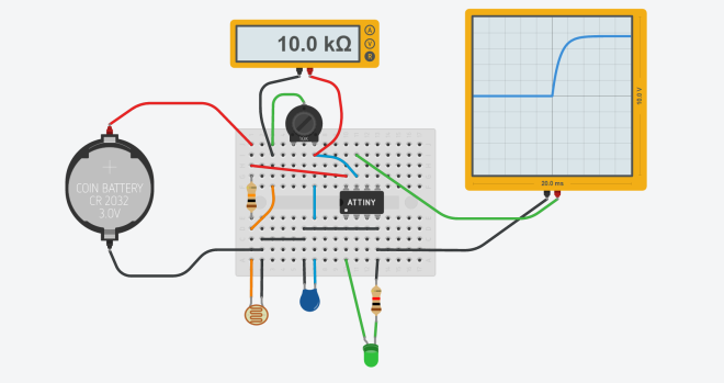
A very basic circuit for that is shown below:

schematixc


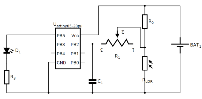
Here a photo-resistor is connected to the bottom half of a voltage divider. The center-tap from the voltage divider is fed into a RC circuit to debounce the output of the photo-resistor. This debounced signal is fed into the analog input pin of the ATtiny85 microcontroller. The microcontroller reads the value of this analog input pin every few milliseconds and determines whether the signal has changed or not. When the signal drops below the 3v, it sets the digital output pin PB5 to LOW, turning off the LED. When the signal returns to a voltage above 3v, it sets the output to HIGH, turning on the LED.

You can try out the circuit by clicking on “Start Simulation”  and then selecting the photo-resistor to change it’s value. You will observe the LED turn ON and OFF as you play with the photo-resistor values.

https://circuits.io/circuits/849806-iot-light-sensor/embed#breadboard

I will soon update the post with more details about how the RC circuit helps us solve debouncing issues with sensors like photo-resistors.

Light Sensor with Attiny85 and a photo-resistor

Nerfors are online!!!

Recently, I got my hands on four pieces of dirt-cheap radio modules – the nrf24L01s or the Nerfors as I like to call them. After watching them rot on my table for a while (they unfortunately don’t rot away like the fruits), I finally decided to do something about them. And not to mention a dear old friend who never misses a chance to say “Dude, just f@#king finish something!”.

IMG_0175
Nerfors: NRF24L01 modules attached to Arduinos

So here is what I am going to do. I am going to bring these Nerfors online. Then I am going to get three of these Nerfors (the Leaf node devices) to communicate with my raspberry pi (the Gateway node device). Then I am going to get my raspberry pi to host a web server that will allow me to talk to each of the leaf nodes and receive status updates from them over a HTML5 page. Then I am going to give some work to the leaf nodes (rather than just let them send “oinks”). I have a couple of temperature probes lying around. I have a couple of servos lying around. Plenty of work for the nodes.

But the real work will be to control the brightness of an LED lamp. I will talk about this little project of mine soon. Like any other unfinished project of mine, it is waiting for the trainman to come and pick it up. Some of them have been waiting for a long long time.

Here are some technical details about the Nerfors.

nrf24l01_connection_bb

The connections are as follows:

  • GND – Arduino GND pin
  • VCC – Arduino 3.3V pin
  • CE – Arduino digital pin 9
  • CEN – Arduino digital pin 10
  • CLK – Arduino digital pin 13
  • MOSI – Arduino digital pin 11
  • MISO – Arduino digital pin 12

You will notice there is a capacitor connected across the VCC and GND pins of the radio module. This capacitor is needed to allow the radio module to pull current more efficiently from the Arduino. This is necessary when the module is transmitting, as there are very short duration current spikes during transmission that the Arduino cannot handle very well. The capacitor stores the current and discharges whenever the module needs more current.

Here is the video of two nerfors talking to each other:

Nerfors are online!!!