As part of a larger project, I need a light sensor that can provide a digital pulse whenever the photo-resistor output drops (which means that something obstructed the light source it is exposed to).
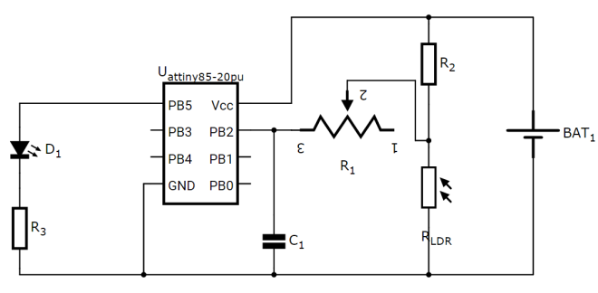
A very basic circuit for that is shown below:

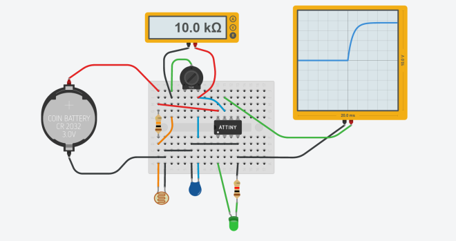
Here a photo-resistor is connected to the bottom half of a voltage divider. The center-tap from the voltage divider is fed into a RC circuit to debounce the output of the photo-resistor. This debounced signal is fed into the analog input pin of the ATtiny85 microcontroller. The microcontroller reads the value of this analog input pin every few milliseconds and determines whether the signal has changed or not. When the signal drops below the 3v, it sets the digital output pin PB5 to LOW, turning off the LED. When the signal returns to a voltage above 3v, it sets the output to HIGH, turning on the LED.
You can try out the circuit by clicking on “Start Simulation” and then selecting the photo-resistor to change it’s value. You will observe the LED turn ON and OFF as you play with the photo-resistor values.
https://circuits.io/circuits/849806-iot-light-sensor/embed#breadboard
I will soon update the post with more details about how the RC circuit helps us solve debouncing issues with sensors like photo-resistors.
